1:1 Current Choke
Up to now, I had fed most of my antennas directly with coax. Doing eSSB I wanted to keep as much common mode (RF) out of the shack and help keep the RF on the antenna where it belongs anyway. I suppose it is good engineering to do this anyway, so I started looking into ways of doing this.
The 1:1 choke is the device, but there are different ways to achieve this. The infamous "ugly balun" (Or is it really an unun?) is one way. It requires no additional parts, just wind the coax at the antenna on a form. 12 turns of RG-8 on a 5 inch form is about 18μH at 160m. That means just over 15 1/2 feet of coax is used to make the choke. With prices usually running about $1.20/ft, that's around $20 in feedline and you still need the PVC form and end caps to make a nice choke that will last. My estimates as of January 2022 put that at about $30. It is also a considerable amount of weight at the center of an antenna.
200ohm of impedance is needed to choke the common mode currents from the shield of coax. The inductance necessary for that value changes with frequency.
Inductance needed for 200 Ohms of reactance at frequency:
1.8 MHz = 18μH
3.8 MHz = 10μH
7.2 MHz = 5μH
Fair Rite mix 31 toroids (pn 2631803802) and RG-316 coax was chosen for this project. Digi Key sells them for $9.84 each. So for about the same cost in materials, you can wind a 1:1 current choke that is much lighter than the ugly "balun".
This seems to be known by several names when looking around the web. Unun, Guanella Unun(not balun), Current Choke, and maybe others. The idea is not matching a balanced line to an unbalanced line, so it is not a balun. The primary function is to keep RF currents from flowing on the outside of the feedline (common mode).
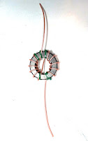
The image at the top of page is a single core wrapped with RG316, this would be sufficient for up to around 500w, but I want to have the headroom for more power later, so I will be winding mine on two cores. This gives more heat tolerance for mismatched loads at the higher power levels.
So below are photos of my idea for an enclosure for the choke and the center of the fan dipole.
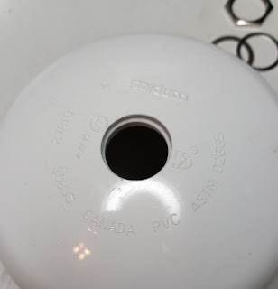
The first order of business is installing a connector into the lower cap. This required using a step drill to create a opening with a lip of the correct depth to allow the washer and nut to be installed inside. The connector requires a 5/8" whole. The step drill allows for the larger recess so the connector sets into the plastic cap.
Stainless eye bolts are then installed to facilitate hanging and connection to each side of the antenna. There will be wires connected to the RG316 coax passed through the sides to make electrical connection to the antenna elements.
This is as far as I have progressed. I will have to cut a piece of pipe to glue both caps together. I still need to wrap the cores together and wind the current choke. I will post photos as I progress.
UPDATE: Yeah, it's a hobby and it's been two years, HIHI.
I finished the choke, finally.
I stacked two of the cores and wrapped them together with Teflon
thread tape and wrapped them as shown in the first photo, 12 turns of the RG-316.
I used 100% silicone caulk to hold the choke in the housing.


Comments
Post a Comment
I welcome comments, keep it on topic. Inappropriate comments will be removed.